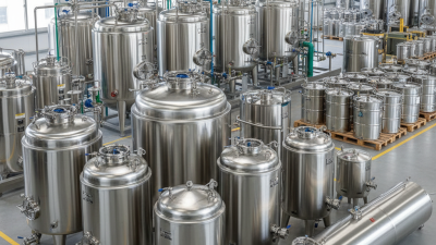
Choosing the right mixing tank is rarely a simple matter of selecting volume and motor power. A tank that looks suitable on paper may produce dead zones, excessive foam, or uneven temperature distribution during real production. Product viscosity, density, solids content, batch size, cleaning requirements, and available floor space all influence the final design. Small details matter.
Edward L. Paul, a leading authority on industrial mixing and co-author of Handbook of Industrial Mixing, states, “Mixing is the process of reducing or eliminating nonuniformities in a material.” That principle remains practical today. A reliable mixing tank should create consistent results without damaging sensitive ingredients or wasting energy. Operators should examine impeller position, shaft length, baffle design, heating surfaces, and drainability. Ask for documented test data, not attractive photographs. Supplier experience also matters, especially for abrasive slurries, high-viscosity products, or hygienic processing.
Real conditions often expose weak decisions. A tank may work well with water but struggle with syrup, cream, or mineral slurry. That is easy to overlook. Pilot trials can reveal poor circulation, unexpected vortexing, or cleaning difficulties before installation. Engineers should also verify materials, seals, controls, and maintenance access with qualified professionals. No single configuration fits every process. The best choice balances performance, safety, operating cost, and future capacity. Even experienced teams can misjudge viscosity changes during heating or cooling. Recheck the assumptions. Then compare the seven practical considerations discussed in this guide before approving your next mixing tank.
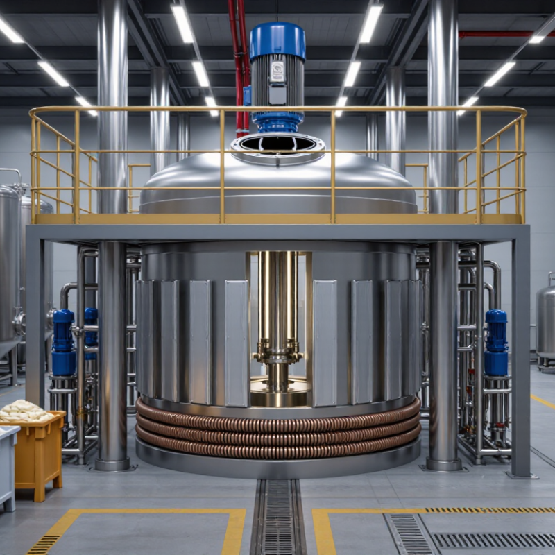
Choosing the right mixing tank starts with defining the process volume, not the tank’s advertised capacity. Record the minimum, normal, and maximum batch sizes before selecting equipment. A tank should usually operate at 70–80% working fill. This range leaves useful headspace for foam, splashing, thermal expansion, and safe agitation. Too little liquid can expose the impeller. Too much can cause overflow.
Viscosity must be measured at the actual processing temperature. A thin liquid may mix easily, while a syrup-like material can demand far more torque. Note whether viscosity changes during heating, cooling, dilution, or reaction. These details influence impeller type, motor sizing, shaft strength, and mixing time. A practical check is to observe the surface, circulation pattern, and dead zones during a controlled trial. Small details matter.
I have seen tanks selected from volume alone. That approach often creates expensive problems. A vessel may hold the batch but still mix it poorly. High-viscosity products may need slower speeds and stronger circulation. Low-viscosity liquids may require baffles to prevent a central vortex.
Leave room for improvement. Your first estimate may be wrong after testing. Document the results, including temperature, fill level, mixing time, and power demand. Reliable records make later scale-up more defensible and easier to adjust.
Choosing the right mixing tank starts with the impeller, not the vessel. Flow pattern, viscosity, solids content, and shear sensitivity should guide the geometry. Axial-flow impellers move liquid vertically and suit blending or suspension. Radial-flow designs create stronger lateral circulation and dispersion. The U.S. Department of Energy reports that pumping systems may represent 25–50% of industrial facility energy use, so inefficient circulation can become an expensive design mistake.
Tip 1: Match tip speed to the process. A practical range is 3–10 m/s. Use the lower end for gentle blending, fragile particles, or shear-sensitive products. Use higher speeds for dispersion and faster turnover, but check heat generation and vortex formation. The 2023 AIChE mixing guidance emphasizes evaluating power per volume, not speed alone. A larger impeller at moderate rpm may outperform a small, fast impeller. That is easy to overlook.
Tip 2: Confirm the flow regime. Calculate Reynolds number before selecting the motor. Low-Reynolds fluids need torque, while turbulent fluids need circulation and power control.
Tip 3: Test the uncomfortable assumption. A tank that looks well mixed from the surface may contain stagnant zones near the bottom. Add tracer testing, CFD, or a pilot trial when quality risk is high. ISO 10628 process documentation principles also support recording operating conditions, geometry, and verification results. In practice, one trial often exposes what calculations miss.
Motor selection should begin with power density, not tank volume alone. The usual industry range is 0.1–10 kW/m³. Low-viscosity liquids often need the lower end, while thick, heat-sensitive, or difficult blends may require more power.
Tip: Calculate the working volume first. Multiply it by the selected kW/m³ value. A 5 m³ tank at 2 kW/m³ needs about 10 kW of mixing power. However, this figure may represent shaft power, not the motor nameplate rating. Account for gearbox and transmission losses.
A neat calculation can still mislead. Viscosity, solids concentration, impeller diameter, and speed strongly affect actual performance. During testing, watch the liquid near the tank wall and bottom. Dead zones, floating powder, or a slow surface vortex can reveal insufficient circulation.
Tip: Do not choose maximum power automatically. Excessive speed may create foam, heat, or unnecessary shear. Start with the process target, then verify torque and startup conditions. A full tank can demand much more torque than an empty one.
Tip: Leave practical adjustment capacity. A variable-speed drive can help operators refine mixing after installation. This matters because laboratory behavior does not always match production conditions. Record viscosity and batch temperature during trials. Small details matter. A qualified process engineer should review the final selection.
Choosing the right mixing tank starts with the liquid, impeller, and operating speed. Calculate Reynolds number using Re = ρND²/μ, where density, speed, diameter, and viscosity define the flow regime. Below Re 10, viscous forces dominate. Mixing is gentle and highly laminar.
Above Re 10,000, turbulent flow usually controls the vessel. Blending improves, but power demand can rise sharply. The U.S. Department of Energy’s Motor Systems Market Assessment estimated that motor-driven systems consumed about 60–70% of industrial electricity. That figure makes regime verification more than a laboratory exercise. It affects operating cost, heat generation, and motor sizing.
Do not trust speed alone.
A low-speed impeller may still create turbulence in a thin liquid. A fast mixer can remain laminar in syrup. Check Reynolds numbers at minimum and maximum batch conditions, especially when temperature changes viscosity. A transition value between 10 and 10,000 deserves caution; published correlations often vary with tank geometry and baffles. In practice, I would test a small sample, inspect blending time, and compare torque readings. A clean calculation can still miss dead zones near the tank wall. That is where experience matters. The final selection should match the actual fluid, not an idealized datasheet.
Choosing the right mixing tank starts with the product, not the catalogue photo. Check chemical compatibility, viscosity, solids content, and cleaning agents before selecting steel, plastic, or lined construction. A material that looks suitable may swell, pit, or contaminate the batch. Ask for documented compatibility data at actual operating concentrations. Small details matter.
Temperature changes can alter viscosity and mixing performance. Define normal, minimum, and upset temperatures. Pressure ratings must cover vacuum conditions, blocked vents, and thermal expansion. Do not size the vessel only for its average batch. Leave practical headspace for foam and splashing. Agitator power, impeller type, and baffle design should match the process, not simply the tank volume. I have seen tanks meet volume targets yet produce dead zones.
Sanitation requirements need clear thinking. Use smooth internal surfaces, drainable geometry, suitable seals, and cleanable connections. Confirm whether manual cleaning, circulation cleaning, or sterilization is required. For flammable vapors or combustible dust, review ATEX zoning, grounding, bonding, ventilation, and certified electrical equipment with qualified specialists. Document every assumption. One weakness remains common: teams often approve a tank before testing the hardest product condition. A small pilot trial can reveal settling, overheating, or excessive foam before installation.
| No. | Selection Dimension | What to Evaluate | Practical Guidance and Typical Data | Recommended Verification |
|---|---|---|---|---|
| 1 | Define the Process and Mixing Duty | Identify the liquid viscosity, solids content, density, batch volume, required blending time, and whether the process requires blending, suspension, dispersion, emulsification, or gas-liquid mixing. | Specify minimum, normal, and maximum working volume. Account for headspace to prevent splashing, foaming, and vortexing. High-viscosity products generally require a different impeller and drive arrangement than low-viscosity liquids. | Provide the supplier with viscosity in mPa·s, density in kg/m³, particle size, solids loading, and target mixing time. Request a process calculation or mixing test when scale-up risk is significant. |
| 2 | Select Suitable Materials | Check chemical compatibility, corrosion resistance, product contact requirements, weldability, abrasion resistance, and the effect of cleaning chemicals. | 316L stainless steel is commonly selected for many hygienic and corrosive process applications, but it is not universally resistant. Chloride-containing solutions can cause pitting and stress-corrosion risks. Non-metallic linings or specialty alloys may be necessary for aggressive chemicals. | Review chemical concentration, exposure time, temperature, and chloride level. Confirm material certificates, gasket compatibility, weld quality, and corrosion data for the actual process fluid. |
| 3 | Match Temperature Requirements | Consider normal operating temperature, start-up and shutdown conditions, heating or cooling rate, thermal cycling, heat-transfer surface area, and insulation requirements. | The design temperature should be higher than the maximum credible operating temperature and should include process upsets where appropriate. Heating jackets, internal coils, or external heat exchangers must be sized for the required heat-transfer duty. | Document operating and design temperatures separately. Check thermal expansion, gasket limits, jacket pressure and temperature ratings, insulation surface temperature, and control-system response. |
| 4 | Confirm Pressure and Vacuum Rating | Evaluate internal pressure, vacuum conditions, jacket pressure, gas blanketing, blocked outlets, relief scenarios, and pressure fluctuations caused by temperature changes or mixing. | A tank intended only for atmospheric service may not be suitable for vacuum or pressurized operation. Vacuum service requires an appropriate shell, stiffening design, and vacuum protection. Relief devices must be selected for credible overpressure scenarios. | Specify design pressure and full-vacuum or partial-vacuum requirements for the vessel and jacket. Verify calculations, pressure-relief sizing, vacuum-breaker settings, and applicable local pressure-equipment regulations. |
| 5 | Design for Sanitation and Cleanability | Assess clean-in-place (CIP), sterilize-in-place (SIP), drainability, dead legs, surface finish, gasket design, spray coverage, and access for inspection. | For many hygienic applications, product-contact surfaces are specified with a smooth finish such as Ra ≤ 0.8 µm, subject to the applicable process standard. The vessel should drain effectively, minimize crevices, and avoid unnecessary internal supports or uncleanable connections. | Request CIP flow rate, pressure, temperature, chemical concentration, and spray-device coverage data. Verify drainability, weld inspection, surface-finish records, gasket materials, and cleaning-validation requirements. |
| 6 | Evaluate ATEX and Explosion Protection | Determine whether flammable liquids, vapors, gases, or combustible dusts can be present and identify the hazardous-zone classification around the tank and connected equipment. | Typical gas or vapor zones are Zone 0, Zone 1, and Zone 2; dust zones are Zone 20, Zone 21, and Zone 22. Equipment selection must match the zone, gas or dust group, temperature class, equipment category, and required protection level. | Complete a formal hazardous-area assessment. Verify motor, gearbox, instruments, electrical connections, earthing and bonding, static-control measures, ventilation, inert-gas systems, and conformity documentation under the applicable ATEX requirements. |
| 7 | Check Mechanical Reliability and Lifecycle Cost | Review agitator speed, torque, power, shaft design, seal type, bearing arrangement, vibration, maintenance access, spare parts, and total operating cost. | Variable-speed drives can improve process control but must be correctly sized for starting torque and the full viscosity range. Mechanical seals should be selected for pressure, temperature, product properties, and cleaning conditions. Avoid sizing the motor only for normal load. | Request the agitator power, torque curve, critical-speed review, seal plan, vibration limits, preventive-maintenance schedule, energy estimate, and a list of recommended wear parts. |